
This module is a part of a larger series of networking labs using GNS3 in Proxmox. Click here to be taken back to the first pages in the series.

Previous Lab

Reference Material
I'll be following along with this series of labs published by University of the Pacific for their COMP 177 class. The labs were originally published in 2020, but still offer some very valuable educational material.
 University of the Pacific
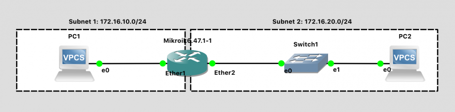
The instructors have also provided us a brief introduction to working with MikroTik's RouterOS.
University of the Pacific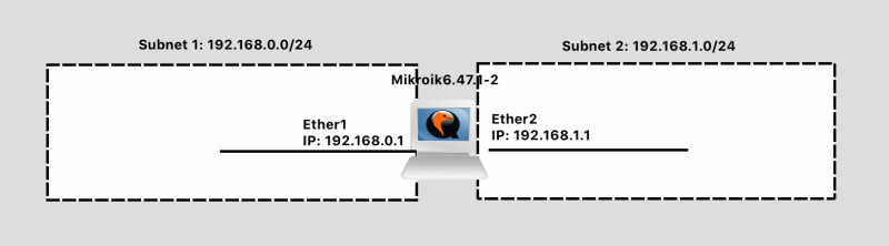
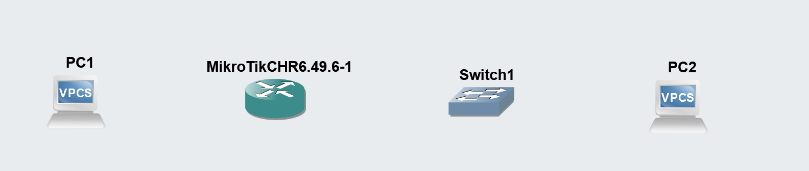
The Network Topology
Based on the lab documentation, we should have:

- Two VPCs
- One MikroTik Router
- One switch
Completing the Project
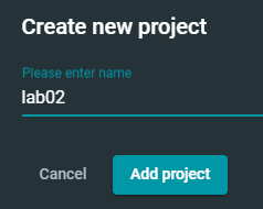
Create a New Project in GNS3

Building out the Network
Click the + button and reveal the node options. I've highlighted the node types we'll need to add to the work area in red.
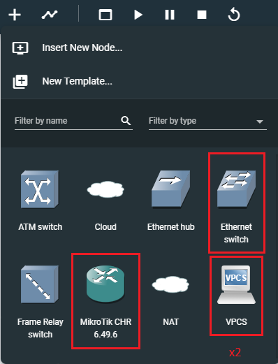
Drag and drop each item onto the canvas to add it to the network environment. You can see that my environment matches the network diagram above. However, I have not yet added any links between the hosts.
Linking the Nodes
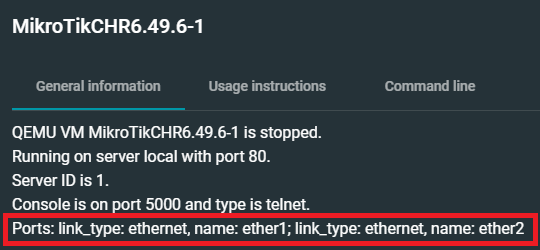
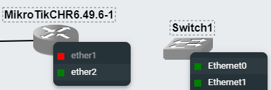
Just a brief detour to look at the MikroTik device... If you right-click the device and choose Show node information, you can see that the router ships with two ports.
Use the Add a link button to wire up the devices in your lab.

Link PC1:Ethernet0 to MikroTik:ether1.
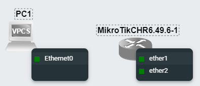
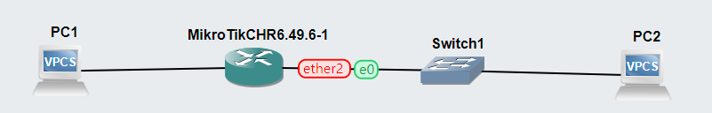
Link MikroTik:ether2 to Switch1:Ethernet0.
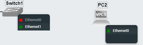
Link Switch1:Ethernet1 to PC2:Ethernet0.
Final result.
Starting and Configuring the Nodes
We'll press the Start button to start all of the nodes at once.

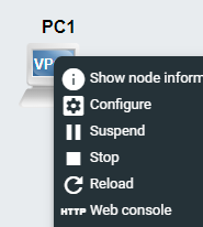
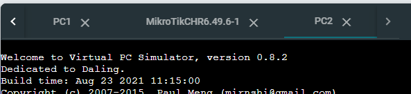
Next, right-click each node and choose Web console. The switch does not have a console, as it is not a managed switch.
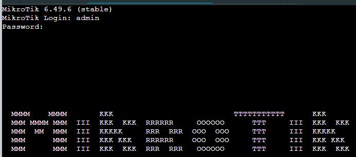
Configure MikroTik
Login with the username admin and a blank password. Choose n when prompted to view the license. You should be prompted to change the admin password.
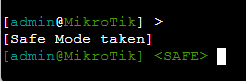
Press CTRL + X to enter safe mode (as advised in the lab documentation).
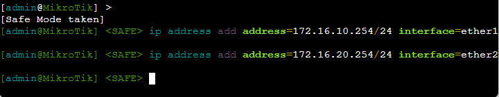
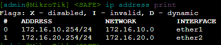
Next, we will run two commands to configure the interfaces with IP addresses. You'll recall this router has two interfaces:
ether1— which is connected toPC1- And,
ether2— which is connected to the switch
Configure Ether1
ip address add address=172.16.10.254/24 interface=ether1ether1is the default gateway forPC1for any communications wherePC1needs to reach another network- We're giving
ether1the following configuration:- IP Address:
172.16.10.254 - Subnet Mask:
255.255.255.0
- IP Address:
Configure Ether2
ip address add address=172.16.20.254/24 interface=ether2ether2is the default gateway for any host plugged intoSwitch1.Switch1is currently just a dumb switch that extends the physical Ethernet medium for the Local Area Network (LAN) of172.16.20.0/24.- We're giving
ether2the following configuration:- IP Address:
172.16.20.254 - Subnet Mask:
255.255.255.0
- IP Address:
Give the Router a Hostname
system identity set name=gns3-mikrotik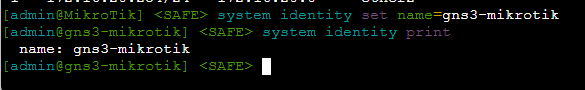
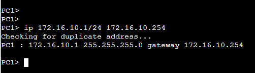
Configure PC1
ip 172.16.10.1/24 172.16.10.254We are giving PC1 the following configuration:
- IP Address:
172.16.10.1 - Subnet Mask:
255.255.255.0 - Default Gateway:
172.16.10.254
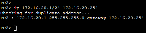
Configure PC2
ip 172.16.20.1/24 172.16.20.254We are giving PC2 the following configuration:
- IP Address:
172.16.20.1 - Subnet Mask:
255.255.255.0 - Default Gateway:
172.16.20.254
Testing Connectivity
You can refer here for a more comprehensive overview of how data travels between two computers, as that's a bit out of scope of this article.
 0xBEN
0xBEN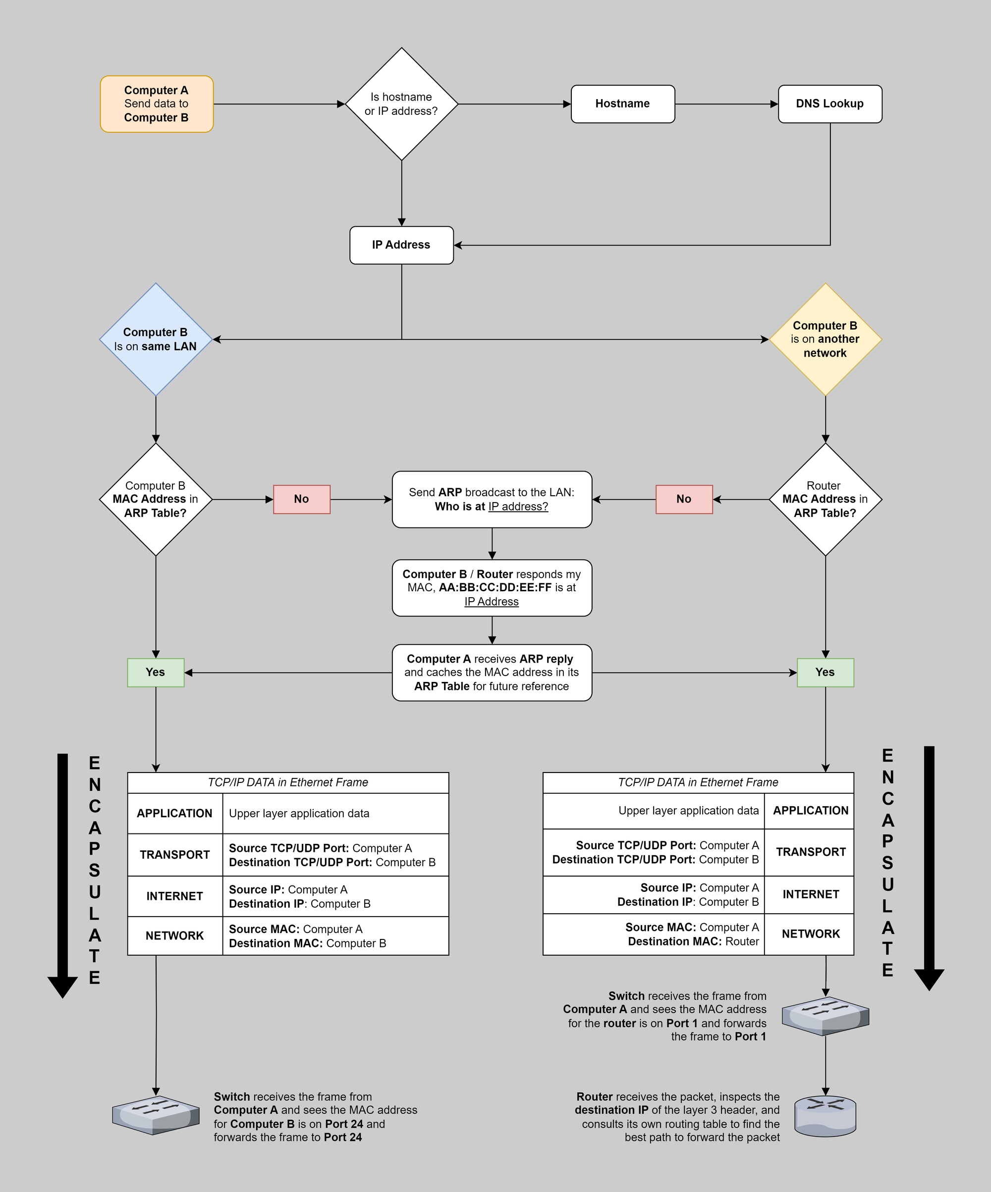
Inspecting Routing Tables
MikroTik
ip route print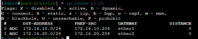
Looking at MikroTik's routing table, you should be able to understand why it will be able to move packets between the PC1 and PC2.
Route 172.16.10.0/24
- MikroTik's routing table has
172.16.10.0/24by way of172.16.10.254onether1interface- So if
PC1is at172.16.10.1and sends a packet to172.16.20.1, this goes to the default gateway (MikroTik) at172.16.10.254for routing - MikroTik sees that
172.16.20.0/24is onether2, checks its ARP table forPC2's MAC address, and puts the packet on the wire to its destination
- So if
Route 172.16.20.0/24
- MikroTik's routing table has
172.16.20.0/24by way of172.16.20.254onether2interface- Likewise if
PC2is at172.16.20.1and sends a packet to172.16.10.1, this goes to its default gateway,172.16.20.254for routing - MikroTik sees that
172.16.10.0/24is onether1, checks its ARP table forPC1's MAC address, and puts the packet on the wire to its destination
- Likewise if
PC1 to Default Gateway
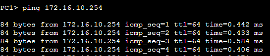
PC1 is pinging the MikroTik ether1 interface, which should have no trouble, as they're both physically linked, and are configured statically with the same network address and subnet mask.
PC2 to Default Gateway
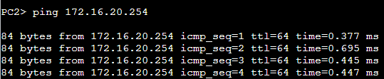
PC2 is pinging the MikroTik ether2 interface. This goes to Switch1, which looks at its CAM table to find the port where the MAC address of MikroTik's ether1 interface is plugged in. Switch1 then forwards the Ethernet frame onto MikroTik.
MikroTik replies, and the process repeats itself in reverse.
PC1 to PC2
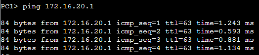
PC1 is pinging a target on a foreign network. It sends the packet to the MikroTik router to complete its destination. The path of the packet is effectively:
ICMP Packet Path
-
Source IP:
PC1
Destination IP:PC2
Source MAC:PC1
Destination MAC:MikroTik ether1 - MikroTik receives the Ethernet frame
- Inspects the packet's destination IP
- The destination route is in the routing table
-
Source IP:
PC1
Destination IP:PC2
Source MAC:MikroTik ether2
Destination MAC:PC2
-
Switch1receives the Ethernet frame- Inspects the destination MAC
- Sends the frame to the port where
PC2is plugged in
-
PC2receives the Ethernet frame- Inspects the destination MAC
- Inspects the destination IP
- The packet has reached its destination
- Time to send an
ICMP replypacket -
Source IP:
PC2
Destination IP:PC1
Source MAC:PC2
Destination MAC:MikroTik ether2
-
Switch1receives the Ethernet frame- Inspects the destination MAC
- Sends the frame onto the port where
MikroTik ether2is plugged in
- MikroTik receives the Ethernet frame
- Inspects the destination IP
- The destination route is in the routing table
-
Source IP:
PC2
Destination IP:PC1
Source MAC:MikroTik ether1
Destination MAC:PC1
-
PC1receives the Ethernet frame- Inspects the destination MAC
- Inspects the destination IP
- The
ICMP replyhas reached its destination
PC2 to PC1
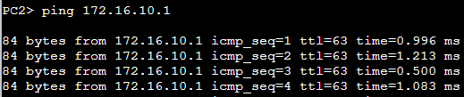
Since we covered the process more in-depth when looking at PC1, I'll summarize the packet path briefly here.
PC2 is pinging a target on a foreign network. It sends the packet to Switch1 — stamped with MikroTik's MAC address — and the switch sends the Ethernet frame to MikroTik. MikroTik routes the packet to its destination.
PC1 responds and the packet goes back to MikroTik, then to Switch1, and then onto PC2.
Up Next: GNS3 Lab 3
The lab 3 blog post is in the works and I'll link to it here as soon as I've finished it. Stay tuned.