
This module is a part of a larger series of networking labs using GNS3 in Proxmox. Click here to be taken back to the first pages in the series.

Reference Material
 University of the Pacific
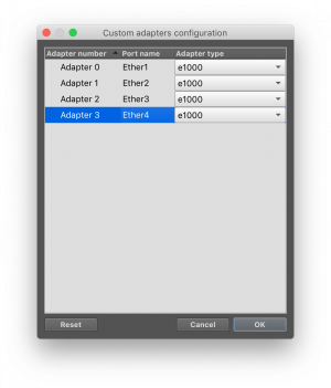
I'll be following along with this series of labs published by University of the Pacific for their COMP 177 class. The labs were originally published in 2020, but still offer some very valuable educational material.
I've already setup GNS3 in Proxmox on the previous blog post, so I will be picking up this lab on Step 5: Install Mikrotik Router into GNS3.
Installing Mikrotik Router
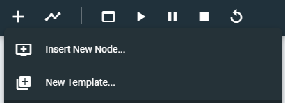
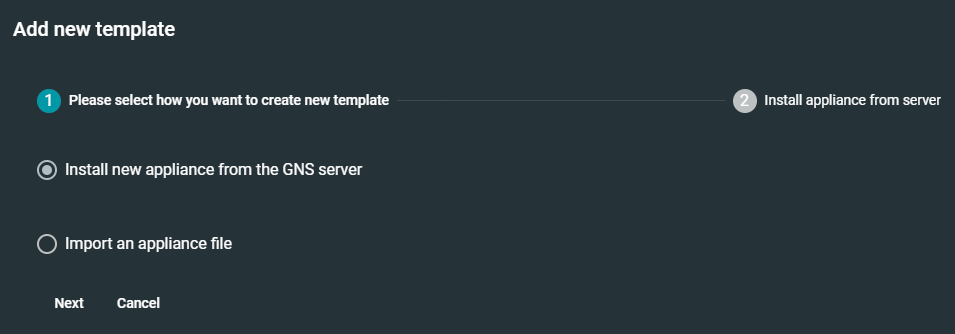
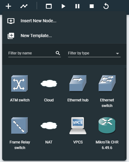
In my browser, I am going to http://gns3-vm-ip-or-fqdn in my browser and using GNS3 from the web interface. The COMP 177 lab documentation tells you to install the router from the Mikrotik download page, but we can use the pre-made templates in GNS3.
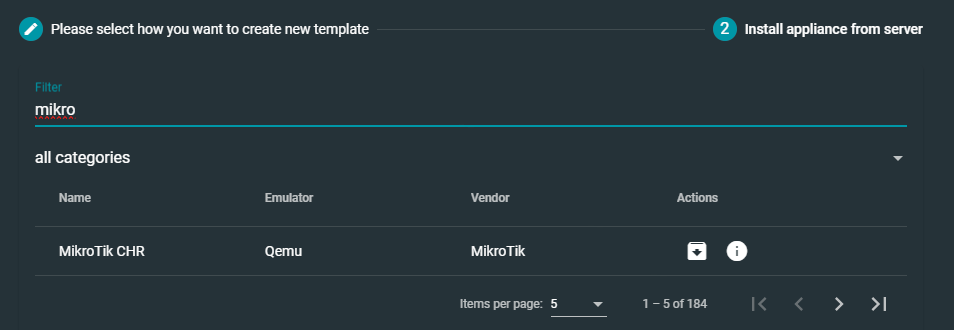
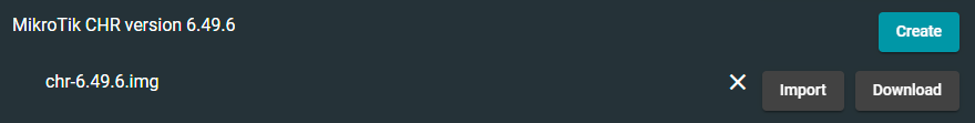
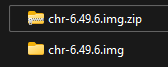
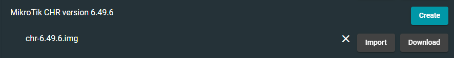


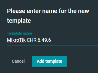
We now have a virtual MikroTik 6.49.6 router that we can use in our GNS3 project topologies.
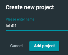
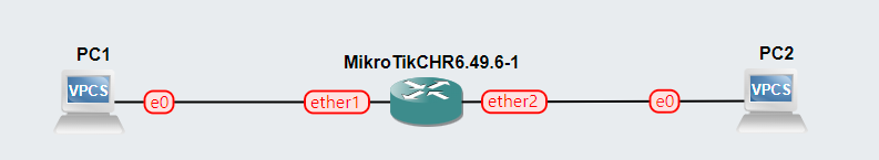
Our First Network
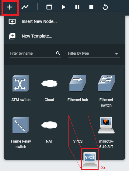
Add the Hosts

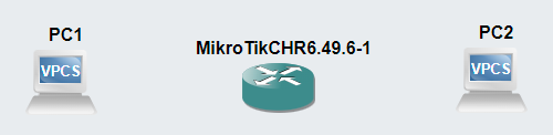
Add the Links


Configure the MikroTik Interfaces
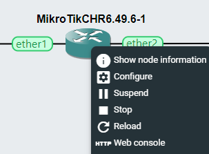
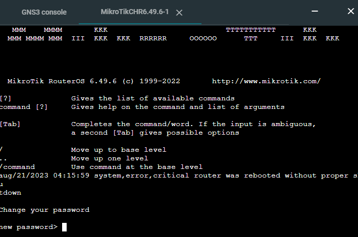
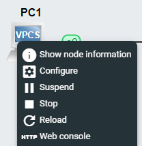
You should now have a console with direct access to the MikroTik command line. You should login with the username admin and an empty password. If prompted, you can decline to view the license. You will also be prompted to change the administrator password.
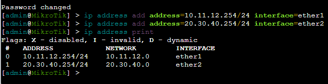
We are configuring the interfaces on the MikroTik. You'll the interface names we're configuring match the interface names in the GNS3 work area, ether1 and ether2.
ether1is the gateway for the10.11.12.0/24network and is configured with the IP address of10.11.12.254and subnet mask of255.255.255.0.ether2is the gateway for the20.30.40.0/24network and is configured with the IP address of20.30.40.254and subnet mask of255.255.255.0.
Configure the VPCs
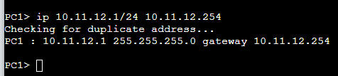
Configure PC 1
We are going to configure PC 1 with an IP address of 10.11.12.1 and a subnet mask of 255.255.255.0, putting it on the same subnet mask as the MikroTik's ether1 interface. We've also set the default gateway as 10.11.12.254.
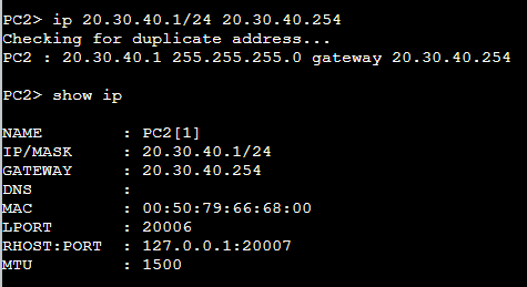
Configure PC 2
We are going to configure PC 2 with an IP address of 20.30.40.1 and a subnet mask of 255.255.255.0, putting it on the same subnet mask as the MikroTik's ether2 interface. We've also set the default gateway as 20.30.40.254.
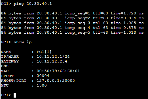
Test the Route
Per the lab instructions, we'll log into PC 1 and send an ICMP request to 20.30.40.1. This IP address is on a foreign subnet, so the packet will be sent to MikroTik's ether1 interface.
MikroTik will then check its routing table to see where to send the packet. 20.30.40.1 is a route that the MikroTik owns, so it moves the packet out on ether2 and onto PC 2.
PC 2 successfully receives the ICMP request and sends an ICMP reply. MikroTik again will be the responsible party for ensuring these two hosts can continue to communicate.

Up Next: GNS3 Lab 2