
Key Points
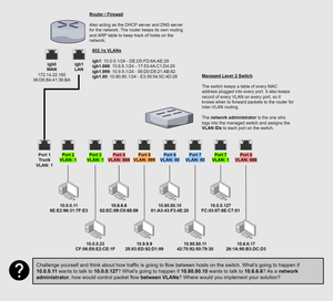
- VLANs are a layer 2 concept. The segmentation is occurring on the switch. The switch needs the assistance of a router – a layer 3 device – to move traffic between VLANs.
- The switch has a database called a CAM table where it keeps track of the following details about every plugged in computer:
- MAC Address
- Port Number
- VLAN ID -- if it's a managed switch
- VLANs require a "managed" switch. That means the switch has an embedded server of some kind where a network administrator will log into and configure each port with the desired VLAN tag number. An "unmanaged" switch – a dumb switch – is much simpler and only serves the purpose of forwarding traffic to the correct MAC address.
- The design in the diagram above is known as "router-on-a-stick" (ROAS), because of the single trunk from the switch to the router. It is a common design in smaller networks.
802.1q Protocol
How Does 802.1q Work?
802.1q – also referred to as Dot1Q – is an open standard developed by the Institute of Electrical and Electronics Engineers (IEEE).
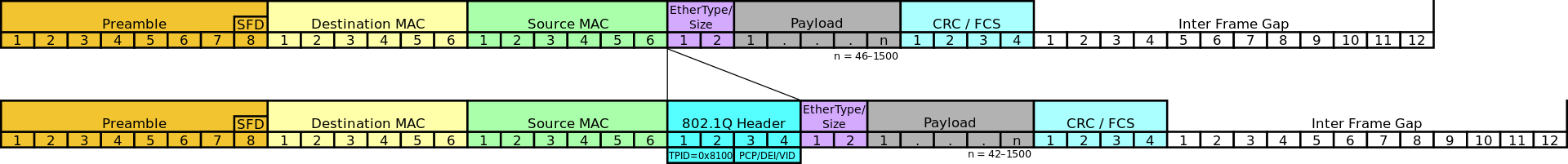
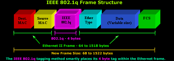
Header Injection
In the picture above, the top picture is a standard Ethernet frame. And, the bottom picture is an Ethernet frame with 802.1q bytes included.
When a computer plugged into the port puts a frame on the wire, the switch will inject the 802.1q header into the Ethernet frame and send it to one of two places:
- The destination host
- The router
We'll cover traffic flow in the section below.
VLAN Segmentation
VLAN segmentation — by itself — is not a security feature. It is a means of breaking up a single physical network topology into smaller logical network segments. When combined with a firewall, you can create a more robust network security design.
How Does Traffic Flow?
Computer Networking Fundamentals
In essence, to transmit a packet, a host needs to know two things:
- The destination IP address
- The destination MAC address
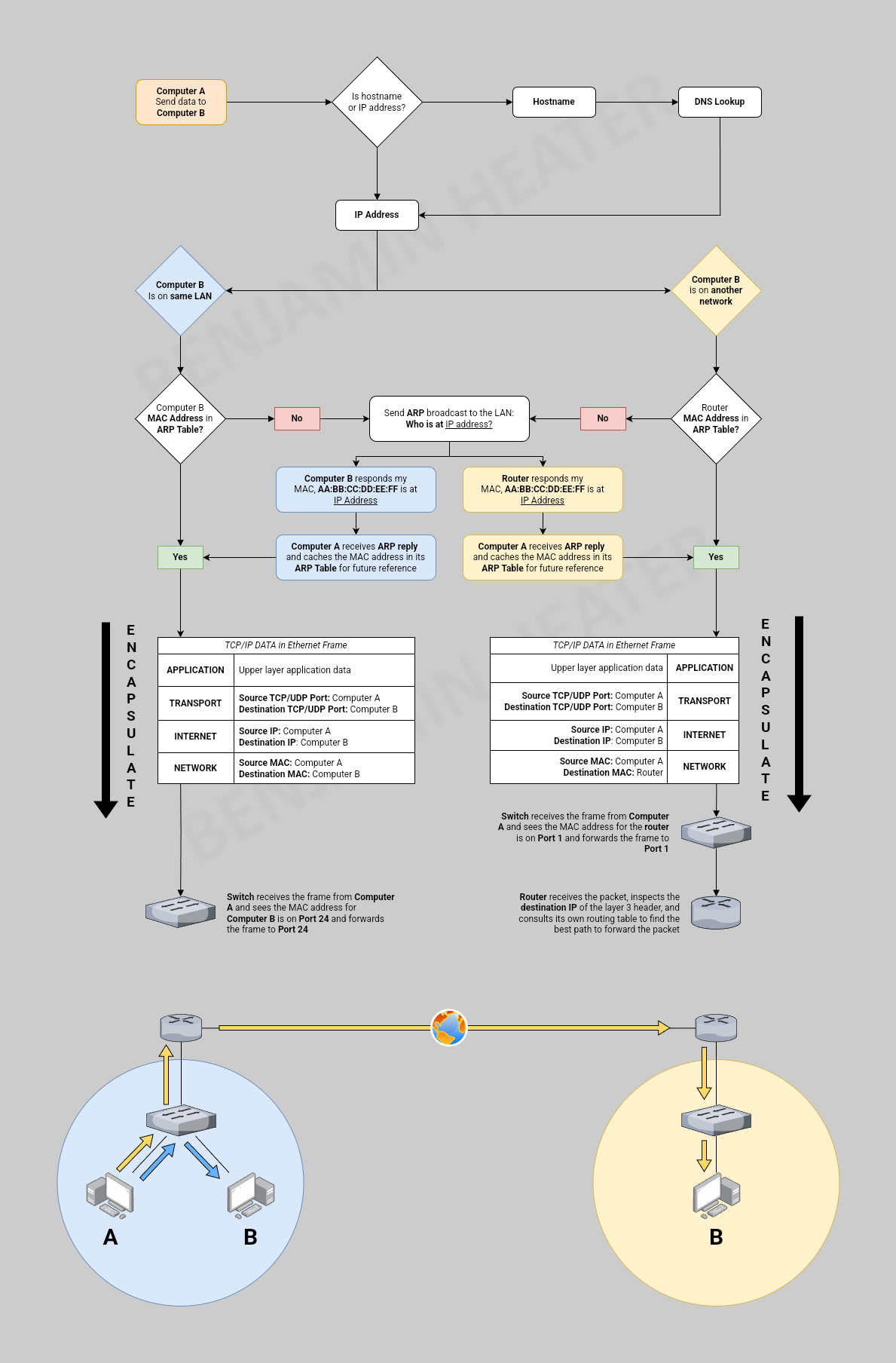
Click here for a quick refresher on sending data between two hosts
Network Diagram
Click here to view this diagram in a new tab
Hosts in the Same VLAN
We'll single out port 6 and port 7 for the sake of this example: 10.80.80.10 sends a packet to 10.80.80.11
- Port 6: VLAN 80
- Host IP address:
10.80.80.10 - Host MAC address:
81:A3:43:F3:4E:20
- Host IP address:
- Port 7: VLAN 80
- Host IP address:
10.80.80.11 - Host MAC address:
42:70:92:50:79:30
- Host IP address:
Traffic Flow
[10.80.80.10] ---> [Switch] ---> [10.80.80.11]TL;DR
Show Details
10.80.80.10sends an ARP discover broadcast on the wire toFF:FF:FF:FF:FF:FFto request the MAC address of10.80.80.11- The switch floods the broadcast only on ports configured with VLAN 80
10.80.80.11replies to10.80.80.10with its MAC address10.80.80.10crafts a frame to put on the wire- Source IP:
10.80.80.10 - Destination IP:
10.80.80.11 - Source MAC:
81:A3:43:F3:4E:20 - Destination MAC:
42:70:92:50:79:30
- Source IP:
- The switch receives the frame
- The destination MAC is in the same VLAN as the source MAC
- The switch transfers the frame to port 7 where
42:70:92:50:79:30is plugged in - The frame has completed its journey
Hosts in Distinct VLANs
In this example, we'll focus on port 4 and port 5: 10.6.6.6 sends a packet to 10.9.9.9
- Port 4: VLAN 666
- Host IP address:
10.6.6.6 - Host MAC address:
02:EC:09:C0:65:59
- Host IP address:
- Port 5: VLAN 999
- Host IP address:
10.9.9.9 - Host MAC address:
25:83:ED:92:D1:89
- Host IP address:
Traffic Flow
[10.6.6.6] ---> [Switch] ---> [10.6.6.1]
                               (router)
[10.9.9.9] <--- [Switch] <--- [10.9.9.1]
TL;DR
Show Details
10.9.9.9is on a foreign subnet, so10.6.6.6sends an ARP discover broadcast on the wire toFF:FF:FF:FF:FF:FFto request the MAC address of the default gateway ---10.6.6.110.6.6.1is a virtual interface designated byigb1.666on the router- The
igb1.666notation indicates that the parent interface isigb1and it is tagged with the VLAN ID666
- The switch floods the broadcast only on ports configured with VLAN 666
10.6.6.1replies to10.6.6.6with its MAC address10.6.6.6crafts a frame to put on the wire- Source IP:
10.6.6.6 - Destination IP:
10.9.9.9 - Source MAC:
02:EC:09:C0:65:59 - Destination MAC:
17:53:4A:C1:D4:29(look carefully)
- Source IP:
- The switch receives the frame
- The destination MAC is in the same VLAN as the source MAC
- The switch transfers the frame to port 1 up to the router
- The router receives the frame and inspects the packet
- The destination IP address is noted as
10.9.9.9 - The router sends an ARP discovery broadcast on
igb1.999toFF:FF:FF:FF:FF:FFto request the MAC address for10.9.9.9 - The switch floods the ARP broadcast only on ports configured with VLAN 999
10.9.9.9responds to10.9.9.1with its MAC address
- The destination IP address is noted as
- The router prepares a frame to put on the wire
- Source IP:
10.6.6.6 - Destination IP:
10.9.9.9 - Source MAC:
17:53:4A:C1:D4:29(again, look carefully) - Destination MAC:
25:83:ED:92:D1:89
- Source IP:
- The switch receives the frame
- The source MAC and the destination MAC are in the same VLAN (999)
- The switch transfer the frame to port 5 where
25:83:ED:92:D1:89is plugged in - The frame has completed its journey
✅ The router and the switch both understand 802.1q
✅ The router and and the switch share the same VLAN IDs
✅ The router is the default gateway for all VLANs
Practical Example
Creating VLANs with pfSense
First let's look at the concept of an interface and subinterfaces. An interface is the physical RJ-45 jack on the device. A subinterface is a software-defined interface on the device. The subinterface – in other words – is not a physical interface.
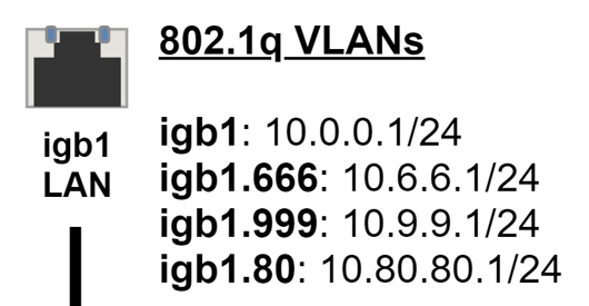
In the network diagram above, the router has two interfaces igb0 and igb1. igb0 is the WAN interface – meaning that all external traffic enters and exits here. igb1 is the LAN interface – meaning that this is the default gateway for all local traffic.
igb1.666, igb1.999, and igb.80 are subinterfaces. They were created by logging into the router and creating these interfaces as subinterfaces of the igb1 interface. In other words, igb1 is the parent interface of these subinterfaces.
Create the VLAN
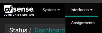
- Log into pfSense. Then, go to
Interfaces > Assignments.
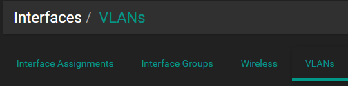
- Click on
VLANs
- Click
Add
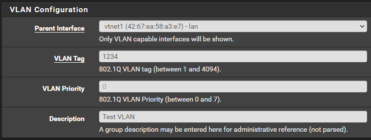
- Configure the VLAN with your details
- Click
Save
Configure the Interface
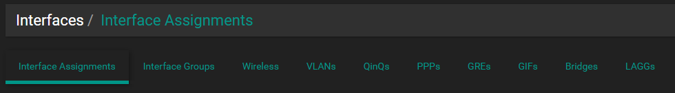
- Go back to
Interface Assignments
- There is a new interface available to be added

- Click
Add

- Click your interface name,
OPT4in my case - Configure it to your liking. Make sure the interface is enabled.
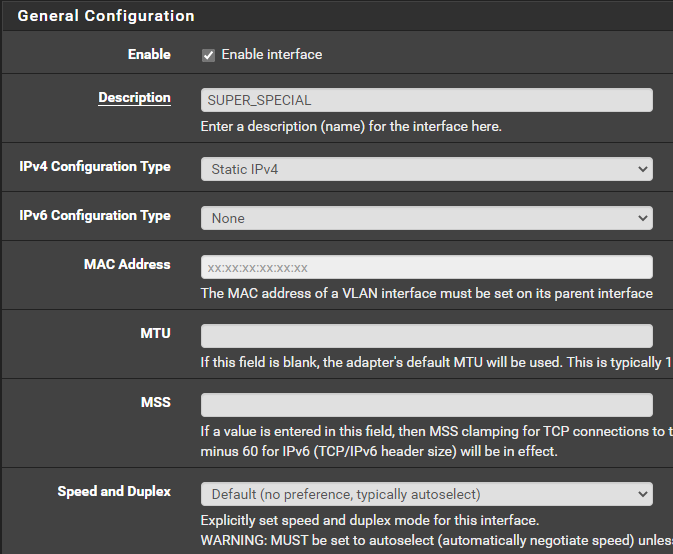
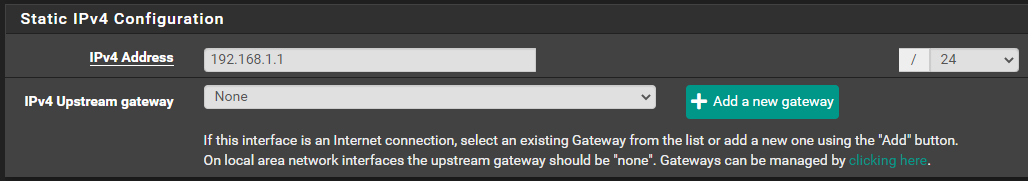
- I have created a
192.168.1.0/24network –/24 = 255.255.255.0. The IPv4 address in this case is the address the default gateway will use. There is no upsteam gateway because this is a LAN. - Click
Save
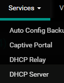
Configure the DHCP Server
- Go to
Services > DHCP Server
- Select your interface name.
SUPER_SPECIALin my case. - Configure your DHCP settings. Make sure to enable the DHCP server.
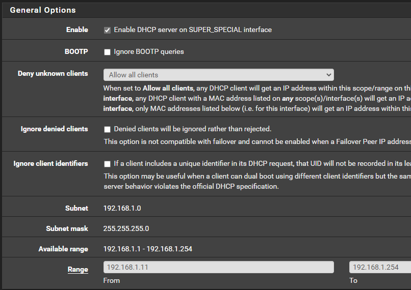
- Click
Saveat the bottom of the screen.
Configure Firewall Rules
- Go to
Firewall > Rules
- Choose your interface.
SUPER_SPECIALin my case - You will notice there are no firewall rules by default
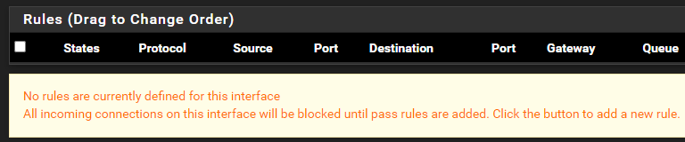
- pfSense is a default deny firewall, so unless you explicitly allow something, it will be blocked.
- Firewall rules are outside the scope of this article, so experiment with it and decide how you want traffic to flow between your networks.
Configure VLANs on the Switch
In the case of the managed switch, if you want a host to be on VLAN 1234, you just need to reconfigure the port with the new VLAN ID.
igb1.1234 and pfSense will assign an IP address from the SUPER_SPECIAL address pool.Additionally, now that the device is on VLAN 1234, any firewall rules you have created will determine how packets may flow. Any other devices on VLAN 1234 will be able on the same LAN, so they can talk freely.
Multi-Switch Architecture
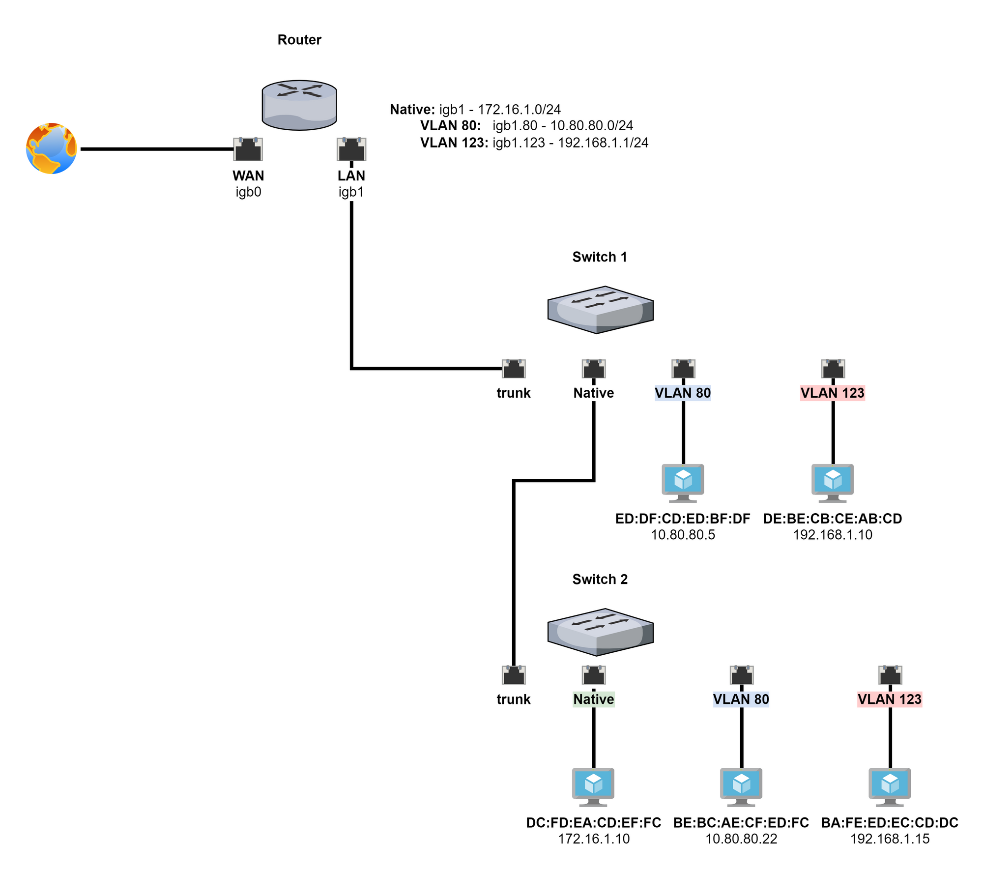
What if you had a multi-switch architecture like this – where switch 1 is the core switch and switch 2 is an access switch? How would hosts communicate?
10.80.80.22 to 10.80.80.5
- They are both on the same logical LAN.
10.80.80.22sends an ARP broadcast toFF:FF:FF:FF:FFto ask for the MAC address of10.80.80.5.- Switch 2 injects the 802.1q payload into the layer 2 headers of the packet.
- The ARP broadcast goes up the trunk to switch 1 and the broadcast is flooded to all ports – on VLAN 80 – on the switch.
10.80.80.5receives the ARP broadcast and replies toBE:BC:AE:CF:ED:FCwith its MAC address –ED:DF:CD:ED:BF:DF.10.80.80.22– which is atBE:BC:AE:CF:ED:FC– then crafts a packet and sets the destination IP address as10.80.80.5and the destination MAC address asED:DF:CD:ED:BF:DF.10.80.80.22sends the packet on the wire. Again, switch 2 injects the 802.1q payload. Switch 1 receives the packet and inspects the frame. It notes the destination MAC is in its table and that they are both in the same VLAN and forward the packet toED:DF:CD:ED:BF:DF.
172.16.1.10 to 192.168.1.10
- They are both on different subnets. This is going to require a router.
172.16.1.10knows the destination is on a different route. It prepares a packet with the destination address as192.168.1.10and the destination MAC address as the default gateway.- Switch 2 receives the packet and inspects the destination MAC address. It is not in its CAM table. It sends the packet up the trunk. Switch 1 receives the packet and checks its CAM table. The destination MAC is in the CAM table on the trunk port. It forwards the packet to the router.
- The router receives the packet and checks the destination address –
192.168.1.10. It checks its ARP table and routing table.192.168.1.10is atDE:BE:CB:CE:AB:CDand is on sub-interface igb1.123. The router injects the 802.1q payload into the layer 2 headers and sends the packet back down the trunk to switch 1. - Switch 1 receives the packet. It inspects the layer 2 headers and notes the destination MAC address of
DE:BE:CB:CE:AB:CD. That is in the CAM table on VLAN 123. It forwards the packet on to its destination.
Deeper Dive on the Subject
Wrapping Up
I hope this has made it easier to understand the concept of VLANs and how the 802.1q protocol can be used to segment devices into smaller LANs. There is much more to explore on this topic, and networking in general.
